Hi folks, thought Id share this in case it helps somebody.
Ive got an old (1935ish) Santianelli 48 bass with some very minor keyboard problems. So I though Id take a break from fixing the valves to see how easy it is to get access to the key mechanism. Ive read AccordionRevival quite a few times and searched on here so after a poke or three I concluded the keys dont come off individually and its a twin axle design. Its got 2 axle ends visible on the bottom end of the keyboard and no holes or axle cover at the top end.
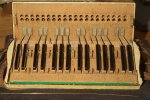
Keyboard: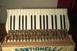
Axles: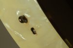
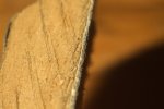
The first axle (upper left one) had the loop protruding just enough to get pliers on it, some twisting and pulling and it came out 2mm so I left it there for the moment. The second axle is the problem: the top of the loop is 2mm below the surface of the celluloid:
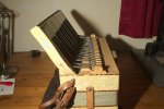
So this is what I did:
1) Widen the hole slightly using a very small modelling scalpel, its now 4mm diameter
2) Push picture wire into the hole and hook it under the cut end of the loop using a jewellers screwdriver
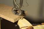
3) Use nail pullers to pull on the wire
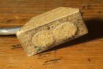
The pulling setup looks like this:
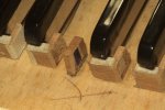
And heres the result:
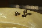
Which should be perfectly acceptable when I put an axle cap on it
Certainly better than drilling a hole in the top end, think I owe myself a beer or four.
Ive got an old (1935ish) Santianelli 48 bass with some very minor keyboard problems. So I though Id take a break from fixing the valves to see how easy it is to get access to the key mechanism. Ive read AccordionRevival quite a few times and searched on here so after a poke or three I concluded the keys dont come off individually and its a twin axle design. Its got 2 axle ends visible on the bottom end of the keyboard and no holes or axle cover at the top end.
Keyboard:

Axles:

The first axle (upper left one) had the loop protruding just enough to get pliers on it, some twisting and pulling and it came out 2mm so I left it there for the moment. The second axle is the problem: the top of the loop is 2mm below the surface of the celluloid:

So this is what I did:
1) Widen the hole slightly using a very small modelling scalpel, its now 4mm diameter
2) Push picture wire into the hole and hook it under the cut end of the loop using a jewellers screwdriver
3) Use nail pullers to pull on the wire
The pulling setup looks like this:

And heres the result:

Which should be perfectly acceptable when I put an axle cap on it
Certainly better than drilling a hole in the top end, think I owe myself a beer or four.
Last edited by a moderator:

