Here is the Quick Disconnect system I installed on my two frontline accordions.
The hardware is designed as a rifle sling QD. There are numerous designs out there. I chose the QD's seen in the pics for two reasons: The flush nature of the accordion side when disconnected and they are stainless steel for corrosion resistance. Not all of this style QD are stainless, some are blued steel and will develop surface rust over time. Avoid Chinese knock-offs as the part tolerances are unacceptable and could separate during use. They come in two strap widths (see "QD's" image); 1 ¼ " (32mm) & 1" ( 25mm), the latter being the preferred width.

There are several designs of interface between the QD socket and the accordion cabinet. Image "QD" shows two options; On the top left, in red, is the smooth barrel, screw retained style. In green is the style I chose. Note the barrel is threaded on the outer surface. While the red version is glued and held in place by one wood (or machine) screw, the green version requires threads be cut into the hole drilled into the cabinet, like a nut. The insert is then twisted into the hole with an Allen wrench (Hex tool).
The red & green are the insert barrels, placed into the holes that must be drilled into the accordion cabinet. The swivel portion, pictured below the inserts, is operated by depressing the detention button with a finger tip. Pressing on the button causes the detent balls to retract into the post on the QD, effectively reducing it's diameter. When inserted into the barrel (as in image on right) and released, the detent balls expand back out into a groove in the barrel, securely locking the two components together.
Drilling the holes is the scariest part of the install. The holes must be sized to the type of unit chosen. When using the threaded style, the appropriate size/pitch tap must also be sourced. Resist the temptation to just screw the barrel into the hole. The wood is hard and the threads on the barrel will expand and crack the cabinet. Drill and Tap only.
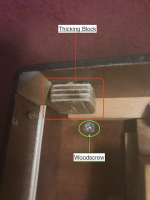
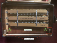
On my box, two of the inserts were drilled into solid wood. The two other inserts are located at a thinner section of the cabinet (see "Internal" image).
In order to provide adequate support for these inserts, I fabricated two "thickening" blocks (Red highlites) and glued them to the inside of the cabinet. The proper glue must be used. The interior of my Baffetti was coated with what I believe to be epoxy. When curing, epoxies leave a surface coating that resists glue's adhesion. Roughing up and cleaning with acetone is advised. Non-coated interior wood should be fine with most adhesives. Once glued, the blocks can be drilled (be careful not to drill thru the block). and tapped, if necessary. With the screw secured style (In red on left, 1st pic), a small machine screw with washer and lock nut would be best here.
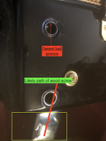
The inserts closest to the keyboard require special attention. As noted in several images, there will be several large (#10) wood screws (in green) that secure the cabinet face to the keyboard plate (Yellow box, "Exterior" image). The two screws of interest are highlighted in green on image "Interior", and elsewhere. These screws will likely be in the most desirable path of the QD Insert hole. This creates a drilling problem to be avoided. Locate the screws and carefully measure their location and transfer said measurements to the surface you intend to drill into. Image "exterior" illustrates where the screw (in red) will likely be located. Both my Baffetti and Beltuna had this screw located in the same place. I used a rare earth magnet, salvaged from a junk hard-drive, to help pinpoint the screws location. This may or may not work, depending on how far the screw is from the cabinet surface. I adjusted the hole locations based on measurements and magnet feedback. Note also on this image, the insert barrel's internal ball detent groove, indicated by red line arrow. The likely path of the wood screw is indicated by the thick red line.
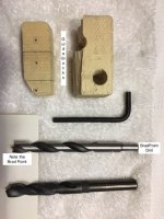
Some notes on drilling. DO NOT use a powered drilling device! The drill can snag on the wood, twist out of alignment, and cause damage. Instead, drill by hand (a somewhat tedious operation, but better safe than sorry. I clamped the drill into a spare drill press chuck I had, which formed a fine handle. Lacking a spare chuck, a cloth scrap tightly wrapped and taped around the shank end of the drill will work. Emphasis on padding the end where it will meet your palm is paramount. Palm pressure will be required to get the drill to advance, wear gloves!. I first drilled a ⅛" (2mm) pilot hole to the desired depth, and then drilled the finish size hole, by hand, using a brad point drill. Do not use a standard metal drill as it will drift off course producing an oval hole (bad). In my case, I then followed up with the proper tap to cut the threads for the insert barrel.
Once the hole was finished and ready to accept the barrel, I mixed and poured a small amount of a thin (read; runny) epoxy resin into the hole. I waited about half the cure time of the epoxy so the resin could saturate the wood surface, removed the excess resin and twisted the barrel insert into the hole until ALMOST flush with the cabinet (I left them a little proud to prevent the swivel portion from rubbing on the cabinet). The reason for the resin treatment was to hopefully reinforce the threads in the wood for a stronger connection. Necessary?, probably not, but I've always been a "belt & suspenders" type of guy, so I went the extra mile.
The cellulose outer layer cause a small issue that took a little while to decipher. The brad point drill cuts around it's outer perimeter, the opposite of a metal drill, which cuts on it's center point, in order to produce a clean splinter free cut. When drilling thru the celluloid, the drill will produce a small "flat washer" like chip that will spin around under the drills cutting edge, stopping progress. The drilling operation must stop and the circular chip removed before drilling can continue.
I applied Scotch "Blue" painters masking tape to the cabinet surface to draw reference lines on and to protect the cabinet surface. Due to a delay procuring the appropriate tap, the tape remained in contact with the cellulose for several days. Upon removal, the adhesive from the tape and the cellulose covering had "commingled", leaving a rough dull surface. Now, this issue may have been a result of the box's cellulose still being "green" with acetone (the box was only 4 weeks from new), or it possibly could happen to even a well "seasoned" instrument. I was able to easily sand out the imperfections with #600 and then #1200 sandpaper, followed by an automotive rubbing compound and then toothpaste (Crest) for a final shine. This entire issue can be avoided by removing any tape applied when the work session is over.
Getting a nice perpendicular hole for the insert barrels:
I took a 2"x3" (50x75mm) wood scrap approximately 11/2" (40mm) thick and drilled holes (one to guide the hole drill and a larger one to guide the tap) of the appropriate diameter, using a drill press. I Then used these 90 degree holes as a guide by placing the guide block on the cabinet's side, inserting the drill thru the guide hole, aligning the drill point with the previously drilled pilot hole and twisting away (while watching the tele). It took a while but the results were worth the effort. I followed the drilling process with a couple of twists of a countersink to remove edge burrs and produce a nice chamfer. I also marked the drill depth with a strip of tape wrapped around the drill body. Remember to account for the guide block thickness. Drill only as deep as required to fit the insert and beware of "breakthroughs" that could result in air leakage. The "hex hole" in my style of insert must be sealed if exposed to the interior of the cabinet.

One unexpected benefit of the system is better stability. The strap ends on a standard mounting system are about ½" (25mm) apart, creating an axis around which the instrument pivots or rotates. The mounting points of the straps with the QD system are separated by several inches (50mm+). This separation reduces the rocking (left to right) moment of the accordion, as there are now two axis' , separated by 2+ inches, making it more stable against the chest. A small but noticeable, and appreciable difference. Strap equipped with QD shown below.

I used hardware acquired from McMillan Stocks at <mcmillanusa.com>. I just visited their website and noted they were currently out of stock, so another source may be required. McMillan was the only source for stainless steel versions I could find. You may do better or find a source in the EU (or Australia, for Dingo).
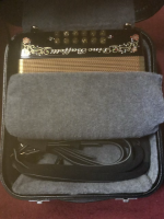
Pic below shows straps disconnected and placed in the case. No strap distortion or straps pinned between the case and the accordion. Allows a quick strap change if a different color strap matches your outfit better.
Well, that about sums it up. The process is simpler than it may seem when reading the above, but I wanted to be thorough and concise. I really like the results for storage purposes as well as I can change straps around quickly if desired. I'll switch from black straps to white sometimes just for the fun of it. R&R time is well less than a minute. Could salvage a gig from a broken strap as well.
Press on....
Waldo
The hardware is designed as a rifle sling QD. There are numerous designs out there. I chose the QD's seen in the pics for two reasons: The flush nature of the accordion side when disconnected and they are stainless steel for corrosion resistance. Not all of this style QD are stainless, some are blued steel and will develop surface rust over time. Avoid Chinese knock-offs as the part tolerances are unacceptable and could separate during use. They come in two strap widths (see "QD's" image); 1 ¼ " (32mm) & 1" ( 25mm), the latter being the preferred width.

There are several designs of interface between the QD socket and the accordion cabinet. Image "QD" shows two options; On the top left, in red, is the smooth barrel, screw retained style. In green is the style I chose. Note the barrel is threaded on the outer surface. While the red version is glued and held in place by one wood (or machine) screw, the green version requires threads be cut into the hole drilled into the cabinet, like a nut. The insert is then twisted into the hole with an Allen wrench (Hex tool).
The red & green are the insert barrels, placed into the holes that must be drilled into the accordion cabinet. The swivel portion, pictured below the inserts, is operated by depressing the detention button with a finger tip. Pressing on the button causes the detent balls to retract into the post on the QD, effectively reducing it's diameter. When inserted into the barrel (as in image on right) and released, the detent balls expand back out into a groove in the barrel, securely locking the two components together.
Drilling the holes is the scariest part of the install. The holes must be sized to the type of unit chosen. When using the threaded style, the appropriate size/pitch tap must also be sourced. Resist the temptation to just screw the barrel into the hole. The wood is hard and the threads on the barrel will expand and crack the cabinet. Drill and Tap only.


On my box, two of the inserts were drilled into solid wood. The two other inserts are located at a thinner section of the cabinet (see "Internal" image).
In order to provide adequate support for these inserts, I fabricated two "thickening" blocks (Red highlites) and glued them to the inside of the cabinet. The proper glue must be used. The interior of my Baffetti was coated with what I believe to be epoxy. When curing, epoxies leave a surface coating that resists glue's adhesion. Roughing up and cleaning with acetone is advised. Non-coated interior wood should be fine with most adhesives. Once glued, the blocks can be drilled (be careful not to drill thru the block). and tapped, if necessary. With the screw secured style (In red on left, 1st pic), a small machine screw with washer and lock nut would be best here.
The inserts closest to the keyboard require special attention. As noted in several images, there will be several large (#10) wood screws (in green) that secure the cabinet face to the keyboard plate (Yellow box, "Exterior" image). The two screws of interest are highlighted in green on image "Interior", and elsewhere. These screws will likely be in the most desirable path of the QD Insert hole. This creates a drilling problem to be avoided. Locate the screws and carefully measure their location and transfer said measurements to the surface you intend to drill into. Image "exterior" illustrates where the screw (in red) will likely be located. Both my Baffetti and Beltuna had this screw located in the same place. I used a rare earth magnet, salvaged from a junk hard-drive, to help pinpoint the screws location. This may or may not work, depending on how far the screw is from the cabinet surface. I adjusted the hole locations based on measurements and magnet feedback. Note also on this image, the insert barrel's internal ball detent groove, indicated by red line arrow. The likely path of the wood screw is indicated by the thick red line.

Some notes on drilling. DO NOT use a powered drilling device! The drill can snag on the wood, twist out of alignment, and cause damage. Instead, drill by hand (a somewhat tedious operation, but better safe than sorry. I clamped the drill into a spare drill press chuck I had, which formed a fine handle. Lacking a spare chuck, a cloth scrap tightly wrapped and taped around the shank end of the drill will work. Emphasis on padding the end where it will meet your palm is paramount. Palm pressure will be required to get the drill to advance, wear gloves!. I first drilled a ⅛" (2mm) pilot hole to the desired depth, and then drilled the finish size hole, by hand, using a brad point drill. Do not use a standard metal drill as it will drift off course producing an oval hole (bad). In my case, I then followed up with the proper tap to cut the threads for the insert barrel.

Once the hole was finished and ready to accept the barrel, I mixed and poured a small amount of a thin (read; runny) epoxy resin into the hole. I waited about half the cure time of the epoxy so the resin could saturate the wood surface, removed the excess resin and twisted the barrel insert into the hole until ALMOST flush with the cabinet (I left them a little proud to prevent the swivel portion from rubbing on the cabinet). The reason for the resin treatment was to hopefully reinforce the threads in the wood for a stronger connection. Necessary?, probably not, but I've always been a "belt & suspenders" type of guy, so I went the extra mile.
The cellulose outer layer cause a small issue that took a little while to decipher. The brad point drill cuts around it's outer perimeter, the opposite of a metal drill, which cuts on it's center point, in order to produce a clean splinter free cut. When drilling thru the celluloid, the drill will produce a small "flat washer" like chip that will spin around under the drills cutting edge, stopping progress. The drilling operation must stop and the circular chip removed before drilling can continue.
I applied Scotch "Blue" painters masking tape to the cabinet surface to draw reference lines on and to protect the cabinet surface. Due to a delay procuring the appropriate tap, the tape remained in contact with the cellulose for several days. Upon removal, the adhesive from the tape and the cellulose covering had "commingled", leaving a rough dull surface. Now, this issue may have been a result of the box's cellulose still being "green" with acetone (the box was only 4 weeks from new), or it possibly could happen to even a well "seasoned" instrument. I was able to easily sand out the imperfections with #600 and then #1200 sandpaper, followed by an automotive rubbing compound and then toothpaste (Crest) for a final shine. This entire issue can be avoided by removing any tape applied when the work session is over.
Getting a nice perpendicular hole for the insert barrels:
I took a 2"x3" (50x75mm) wood scrap approximately 11/2" (40mm) thick and drilled holes (one to guide the hole drill and a larger one to guide the tap) of the appropriate diameter, using a drill press. I Then used these 90 degree holes as a guide by placing the guide block on the cabinet's side, inserting the drill thru the guide hole, aligning the drill point with the previously drilled pilot hole and twisting away (while watching the tele). It took a while but the results were worth the effort. I followed the drilling process with a couple of twists of a countersink to remove edge burrs and produce a nice chamfer. I also marked the drill depth with a strip of tape wrapped around the drill body. Remember to account for the guide block thickness. Drill only as deep as required to fit the insert and beware of "breakthroughs" that could result in air leakage. The "hex hole" in my style of insert must be sealed if exposed to the interior of the cabinet.

One unexpected benefit of the system is better stability. The strap ends on a standard mounting system are about ½" (25mm) apart, creating an axis around which the instrument pivots or rotates. The mounting points of the straps with the QD system are separated by several inches (50mm+). This separation reduces the rocking (left to right) moment of the accordion, as there are now two axis' , separated by 2+ inches, making it more stable against the chest. A small but noticeable, and appreciable difference. Strap equipped with QD shown below.

I used hardware acquired from McMillan Stocks at <mcmillanusa.com>. I just visited their website and noted they were currently out of stock, so another source may be required. McMillan was the only source for stainless steel versions I could find. You may do better or find a source in the EU (or Australia, for Dingo).
Pic below shows straps disconnected and placed in the case. No strap distortion or straps pinned between the case and the accordion. Allows a quick strap change if a different color strap matches your outfit better.

Well, that about sums it up. The process is simpler than it may seem when reading the above, but I wanted to be thorough and concise. I really like the results for storage purposes as well as I can change straps around quickly if desired. I'll switch from black straps to white sometimes just for the fun of it. R&R time is well less than a minute. Could salvage a gig from a broken strap as well.
Press on....
Waldo
